


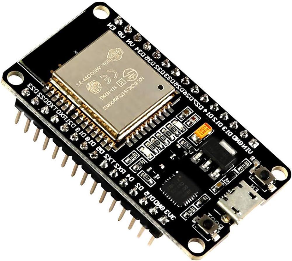
This ESP32 getting started guide is the complete ESP32 beginner guide and ESP32 tutorial for beginners — covering everything from board setup to your first Wi-Fi project. With built-in Wi-Fi, Bluetooth, a dual-core processor, and a generous set of GPIO pins, it offers far more than a standard Arduino board at a comparable price. This guide walks you through everything you need to know to get started with the ESP32 — from understanding the hardware to uploading your first sketch and connecting to a Wi-Fi network.
- Table of Contents
- What is the ESP32?
- ESP32 Key Specifications
- ESP32 vs Arduino Uno: Key Differences
- Popular ESP32 Development Boards
- What You Need to Get Started
- Setting Up the ESP32 in the Arduino IDE
- Project 1: Blink the Built-in LED
- Project 2: Connect the ESP32 to Wi-Fi
- Project 3: Host a Simple Web Server
- Understanding ESP32 GPIO Pins
- ESP32 Power Supply Options
- Common Beginner Mistakes with the ESP32
- What to Build Next with Your ESP32
- Conclusion
- Further Reading and Official Resources
- Related Guides
Table of Contents
What is the ESP32?
The ESP32 is a low-cost, low-power system-on-chip (SoC) microcontroller developed by Espressif Systems. It was released in 2016 as the successor to the popular ESP8266 and quickly became a favourite in the IoT community due to its rich feature set and affordability.
Unlike the Arduino Uno, which requires a separate Wi-Fi or Bluetooth module to communicate wirelessly, the ESP32 has both built directly into the chip. This makes it ideal for IoT projects where devices need to send data to the cloud, communicate with a mobile app, or integrate with platforms such as Home Assistant, Firebase, or MQTT brokers.
ESP32 Key Specifications
| Feature | Specification |
|---|---|
| Processor | Dual-core Xtensa LX6, up to 240 MHz |
| RAM | 520 KB SRAM |
| Flash Memory | 4 MB (on most development boards) |
| Wi-Fi | 802.11 b/g/n (2.4 GHz) |
| Bluetooth | Classic Bluetooth 4.2 and BLE |
| GPIO Pins | Up to 36 (varies by board) |
| ADC | 12-bit, up to 18 channels |
| DAC | 2 channels, 8-bit |
| PWM | 16 channels |
| Communication | SPI, I2C, I2S, UART, CAN |
| Operating Voltage | 3.3V (inputs are NOT 5V tolerant) |
| Deep Sleep Current | As low as 10 µA |
ESP32 vs Arduino Uno: Key Differences
If you are coming from an Arduino background, understanding the differences between the two platforms will help you make the most of the ESP32 from the start.
| Feature | ESP32 | Arduino Uno |
|---|---|---|
| Processor Speed | Up to 240 MHz (dual-core) | 16 MHz (single-core) |
| Wi-Fi | Built-in | Requires external module |
| Bluetooth | Built-in (Classic + BLE) | Not available |
| Operating Voltage | 3.3V | 5V |
| ADC Resolution | 12-bit (0–4095) | 10-bit (0–1023) |
| Price | Similar or lower | Similar |
| IoT Capability | Excellent — built-in connectivity | Limited without add-ons |
One important difference to note: the ESP32 operates at 3.3V logic, not 5V. Connecting a 5V signal directly to an ESP32 GPIO pin can permanently damage the chip. When interfacing with 5V components or sensors, use a logic level converter.
Popular ESP32 Development Boards
The ESP32 chip itself is available on several development board designs. The most common options are:
- ESP32 DevKit V1 — The standard 38-pin development board. The most widely available and documented option. Recommended for beginners.
- ESP32 WROOM-32 — The module variant used on most development boards. Available for custom PCB designs.
- ESP32-CAM — Includes a camera module and SD card slot. Ideal for computer vision and AI-based security camera projects.
- ESP32-S3 — A newer variant with USB OTG support and AI acceleration. Better suited to machine learning applications.
- ESP32-C3 — A single-core, RISC-V based variant designed for lower power consumption in simpler IoT applications.
For this guide, all examples use the standard ESP32 DevKit V1.
What You Need to Get Started
- ESP32 DevKit V1 development board
- Micro-USB cable (for power and programming)
- Breadboard and jumper wires
- LED and a 220-ohm resistor (for the first project)
- Computer running Windows, macOS, or Linux
- Arduino IDE 2 installed (see the Arduino for Beginners guide if you have not done this yet)
Setting Up the ESP32 in the Arduino IDE
The Arduino IDE does not include ESP32 support by default. You need to add the Espressif board package first. Follow these steps:
Step 1: Add the ESP32 Board Package
- Open the Arduino IDE and go to File > Preferences.
- In the Additional Boards Manager URLs field, paste the following URL:
https://raw.githubusercontent.com/espressif/arduino-esp32/gh-pages/package_esp32_index.json - Click OK to save.
Step 2: Install the ESP32 Board Package
- Go to Tools > Board > Boards Manager.
- Search for esp32.
- Find the entry by Espressif Systems and click Install. The installation may take a few minutes.
- Once complete, close the Boards Manager.
Step 3: Select the ESP32 Board and Port
- Connect your ESP32 to your computer via Micro-USB.
- Go to Tools > Board > esp32 and select ESP32 Dev Module.
- Go to Tools > Port and select the COM port corresponding to your ESP32. On Linux or macOS, this will appear as
/dev/ttyUSB0or similar. - Leave all other settings at their defaults for now.
Installing the CP2102 or CH340 Driver
Most ESP32 development boards use either a CP2102 or CH340G USB-to-serial chip. If your computer does not recognise the board after connecting it, you may need to install the appropriate driver. Check which chip is on your board and download the driver from the manufacturer website. Restart your computer after installation.
Project 1: Blink the Built-in LED
Most ESP32 DevKit boards include a built-in LED connected to GPIO 2. This project confirms your setup is working correctly before moving on to more complex tasks.
#define LED_PIN 2

void setup() {
    pinMode(LED_PIN, OUTPUT);
}

void loop() {
    digitalWrite(LED_PIN, HIGH);
    delay(1000);
    digitalWrite(LED_PIN, LOW);
    delay(1000);
}
Click Upload in the Arduino IDE. The IDE will compile the sketch and transfer it to the board. When you see “Done uploading”, the built-in LED should begin blinking once per second.
If the upload fails with a timeout error, hold the BOOT button on your ESP32 board while the IDE is attempting to connect, then release it once the upload begins. Some boards require this to enter programming mode.
Project 2: Connect the ESP32 to Wi-Fi
Connecting to Wi-Fi is where the ESP32 truly separates itself from the Arduino Uno. The following sketch connects to your home Wi-Fi network and prints the assigned IP address to the Serial Monitor.
#include <WiFi.h>

const char* ssid     = "YourWiFiSSID";
const char* password = "YourWiFiPassword";

void setup() {
    Serial.begin(115200);
    WiFi.begin(ssid, password);

    Serial.print("Connecting to Wi-Fi");
    while (WiFi.status() != WL_CONNECTED) {
        delay(500);
        Serial.print(".");
    }

    Serial.println();
    Serial.println("Connected!");
    Serial.print("IP Address: ");
    Serial.println(WiFi.localIP());
}

void loop() {
    // Nothing needed here for this example
}
Replace YourWiFiSSID and YourWiFiPassword with your actual network credentials. After uploading, open the Serial Monitor at 115200 baud and you will see the connection progress followed by the IP address assigned to your ESP32.
Project 3: Host a Simple Web Server
Once connected to Wi-Fi, the ESP32 can host a web server that you can access from any browser on the same network. This example serves a page with two buttons to turn an LED on and off.
#include <WiFi.h>
#include <WebServer.h>

const char* ssid     = "YourWiFiSSID";
const char* password = "YourWiFiPassword";

WebServer server(80);
#define LED_PIN 2

void handleRoot() {
    String html = "<h1>ESP32 Web Server</h1>";
    html += "<a href="/on"><button>Turn LED On</button></a>";
    html += "<a href="/off"><button>Turn LED Off</button></a>";
    server.send(200, "text/html", html);
}

void handleOn()  { digitalWrite(LED_PIN, HIGH); server.sendHeader("Location", "/"); server.send(303); }
void handleOff() { digitalWrite(LED_PIN, LOW);  server.sendHeader("Location", "/"); server.send(303); }

void setup() {
    Serial.begin(115200);
    pinMode(LED_PIN, OUTPUT);
    WiFi.begin(ssid, password);
    while (WiFi.status() != WL_CONNECTED) delay(500);
    Serial.println(WiFi.localIP());
    server.on("/",    handleRoot);
    server.on("/on",  handleOn);
    server.on("/off", handleOff);
    server.begin();
}

void loop() {
    server.handleClient();
}
After uploading, open the Serial Monitor to find the IP address, then type that address into a browser on the same Wi-Fi network. You will see a simple page with two buttons that control the LED remotely.
Understanding ESP32 GPIO Pins
The ESP32 has up to 36 GPIO pins, but not all of them are suitable for general use. Here is what you need to know before connecting components:
- Safe output pins: GPIO 2, 4, 5, 12–19, 21–23, 25–27, 32–33 are safe for general digital input and output.
- Input-only pins: GPIO 34, 35, 36, and 39 are input-only and cannot be used as outputs.
- Strapping pins: GPIO 0, 2, 5, 12, and 15 affect the boot behaviour of the ESP32. Avoid connecting components that pull these pins HIGH or LOW at startup unless you understand the implications.
- ADC2 conflict: ADC2 pins (GPIO 0, 2, 4, 12–15, 25–27) cannot be used for analog readings while Wi-Fi is active. Use ADC1 pins (GPIO 32–39) for analog inputs in Wi-Fi projects.
- 3.3V only: All GPIO pins operate at 3.3V. Do not connect 5V signals directly to any ESP32 pin.
ESP32 Power Supply Options
The ESP32 development board can be powered in several ways depending on your project requirements:
- USB (5V via Micro-USB) — The most convenient option during development. The onboard regulator converts 5V to 3.3V for the chip.
- VIN pin (5V–12V) — Connect an external power supply to the VIN and GND pins when USB is not available.
- 3.3V pin — If your power supply already outputs regulated 3.3V, connect it directly to the 3V3 pin and GND. Do not use this pin as an output to power other components as it draws from the onboard regulator directly.
- LiPo battery — Many ESP32 projects use a 3.7V LiPo battery with a TP4056 charger module for portable, battery-powered deployments.
Common Beginner Mistakes with the ESP32
- Using 5V sensors without a level shifter — The ESP32 is not 5V tolerant. Always use a logic level converter or voltage divider when interfacing with 5V components.
- Selecting the wrong baud rate in the Serial Monitor — ESP32 sketches typically use 115200 baud, not the 9600 that Arduino sketches commonly use. A mismatched baud rate produces garbled output.
- Not pressing the BOOT button during upload — Some boards require you to hold the BOOT button to enter programming mode when the IDE begins connecting. This is normal behaviour on many DevKit variants.
- Using ADC2 pins with Wi-Fi active — Reading analog values from ADC2 pins while Wi-Fi is running returns inaccurate or erratic values. Always use ADC1 pins (GPIO 32–39) for analog readings in connected projects.
- Blocking the loop with long delays — Using
delay()in the main loop prevents the ESP32 from handling Wi-Fi tasks and web server requests. Usemillis()-based timing for non-blocking delays in Wi-Fi projects.
What to Build Next with Your ESP32
With the basics in place, you have a solid foundation for a wide range of IoT projects. Here are some well-documented next steps available on this site:
- ESP32 with DHT11 / DHT22 — Read temperature and humidity and display or publish the data online.
- ESP32 Firebase Realtime Database — Store sensor data in the cloud and retrieve it from any device in real time.
- ESP32 OTA Updates — Update your ESP32 firmware wirelessly over Wi-Fi without connecting a USB cable.
- ESP32 with MQTT — Integrate your ESP32 into an MQTT-based IoT ecosystem with Home Assistant or Node-RED.
- ESP32-CAM AI Security Camera — Stream live video and detect motion using the ESP32-CAM module.
Conclusion
The ESP32 is one of the most powerful and cost-effective development boards available, and it is an essential tool for anyone serious about building IoT projects. Its built-in Wi-Fi and Bluetooth, combined with full compatibility with the Arduino IDE, makes it equally accessible to beginners and experienced developers alike.
By completing the three projects in this ESP32 tutorial for beginners, you have verified your development environment, confirmed wireless connectivity, and built a functioning web-controlled interface — all with just a few lines of code. From here, the range of projects you can build with the ESP32 is limited only by your imagination.
Further Reading and Official Resources
- Arduino-ESP32 Official Documentation — Espressif’s official guide for using ESP32 with the Arduino framework.
- ESP32 Product Page — Espressif Systems — Datasheets, technical references, and hardware design guidelines.
- ESP32 GPIO Reference — Detailed GPIO pin reference guide widely used by the ESP32 community.
Related Guides
- What is IoT? A Beginner’s Guide to the Internet of Things
- What is MQTT? A Beginner’s Guide to the IoT Messaging Protocol
- Arduino for Beginners: A Complete Getting Started Guide
- Top 5 Development Boards for IoT Projects in 2026
- The Complete ESP32 Pinout Guide: Which Pins to Use?
- ESP32 Deep Sleep Mode: Extend Battery Life in IoT Projects
- Interface DHT11 and DHT22 Sensors with ESP32
