Introduction to NodeMCU
An open-source development board called NodeMCU combines an ESP8266 microprocessor with built-in Wi-Fi. It offers a user-friendly framework for the development and prototyping of the Internet of Things, allowing programmers to create Wi-Fi-enabled products without having a deep understanding of networking protocols. The NodeMCU board has become more well-liked as a result of its low cost, simplicity of usage, and broad community support.
Understanding NodeMCU Pinout
Numerous pins on the NodeMCU development board have diverse purposes. Power pins, analog pins, digital pins, UART pins, I2C pins, SPI pins, and other pins can be used to categorize these pins. Let’s take a closer look at each pin category.
Power Pins
The NodeMCU board’s power pins are in charge of supplying the required electrical power. They consist of:
VV (3.3V): This pin supplies the board and any associated peripherals with a regulated 3.3V power supply.
Vin: Using a 4V to 9V external power supply, you can power the NodeMCU board using this pin.
GND: The board’s common reference voltage is provided by the ground pins.
Analog Pins
There is only one analog pin on the NodeMCU board, designated A0. The analog voltages from external sensors or devices can be measured via this pin.
Digital Pins
11 digital pins (D0 to D10) are available on NodeMCU and can be used for input and output activities. These pins can accommodate digital signals with 3.3V voltage levels.
UART Pins
Two UART (Universal Asynchronous Receiver-Transmitter) pins, marked TX and RX, are available on the NodeMCU board. These pins are used for serial transmission and can be connected to other devices or used for debugging.
I2C Pins
The I2C (Inter-Integrated Circuit) interface on the NodeMCU has just two pins: SDA for serial data and SCL for serial clock. The I2C protocol enables two-wire interface connection with several devices.
SPI Pins
Communication with SPI-compatible devices is made possible by the SPI (Serial Peripheral Interface) pins on the NodeMCU board. It has four pins: SCK (Serial Clock), MOSI (Master Out Slave In), MISO (Master In Slave Out), and SS (Slave Select).
Other Pins
NodeMCU offers a few extra pins in addition to the ones stated above, including the RESET pin for resetting the microcontroller and the D8 pin, which is connected to the board’s integrated LED.
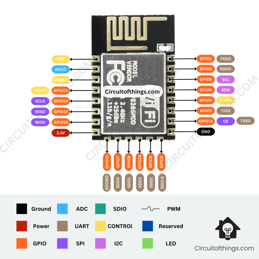
ESP8266 12-E Chip Pinout
Here is an illustration of the pinout for the ESP8266 12-E chip. This diagram is useful if you are using a bare ESP8266 chip in your projects.

| GPIO Pin | Pin Name | Safe for General Purpose | Reason | Additional Information |
|---|---|---|---|---|
| GPIO0 | GPIO0 | Yes | Can be used as a general-purpose I/O pin. | It is a multipurpose pin that can be used for various purposes. It also has a built-in pull-up resistor. |
| GPIO1 | GPIO1 | No | Reserved for UART transmission (TX). | GPIO1 is dedicated to UART communication and should not be used for general-purpose purposes. |
| GPIO2 | GPIO2 | Yes | Can be used as a general-purpose I/O pin. | It is a multipurpose pin that can be used for various purposes. |
| GPIO3 | GPIO3 | Yes | Can be used as a general-purpose I/O pin. | It is a multipurpose pin that can be used for various purposes. |
| GPIO4 | GPIO4 | Yes | Can be used as a general-purpose I/O pin. | It is a multipurpose pin that can be used for various purposes. |
| GPIO5 | GPIO5 | Yes | Can be used as a general-purpose I/O pin. | It is a multipurpose pin that can be used for various purposes. |
| GPIO6 | GPIO6 | Yes | Can be used as a general-purpose I/O pin. | It is a multipurpose pin that can be used for various purposes. |
| GPIO7 | GPIO7 | Yes | Can be used as a general-purpose I/O pin. | It is a multipurpose pin that can be used for various purposes. |
| GPIO8 | GPIO8 | Yes | Can be used as a general-purpose I/O pin. | It is a multipurpose pin that can be used for various purposes. |
| GPIO9 | GPIO9 | Yes | Can be used as a general-purpose I/O pin. | It is a multipurpose pin that can be used for various purposes. |
| GPIO10 | GPIO10 | Yes | Can be used as a general-purpose I/O pin. | It is a multipurpose pin that can be used for various purposes. |
| GPIO11 | GPIO11 | Yes | Can be used as a general-purpose I/O pin. | It is a multipurpose pin that can be used for various purposes. |
| GPIO12 | GPIO12 | Yes | Can be used as a general-purpose I/O pin. | It is a multipurpose pin that can be used for various purposes. |
| GPIO13 | GPIO13 | Yes | Can be used as a general-purpose I/O pin. | It is a multipurpose pin that can be used for various purposes. |
| GPIO14 | GPIO14 | Yes | Can be used as a general-purpose I/O pin. | It is a multipurpose pin that can be used for various purposes. |
| GPIO15 | GPIO15 | Yes | Can be used as a general-purpose I/O pin, but with caution. | It is a multipurpose pin that can be used for various purposes. It has an internal pull-down resistor connected to it, so when used as an input pin, it should be left unconnected or pulled high externally to avoid conflicts. |
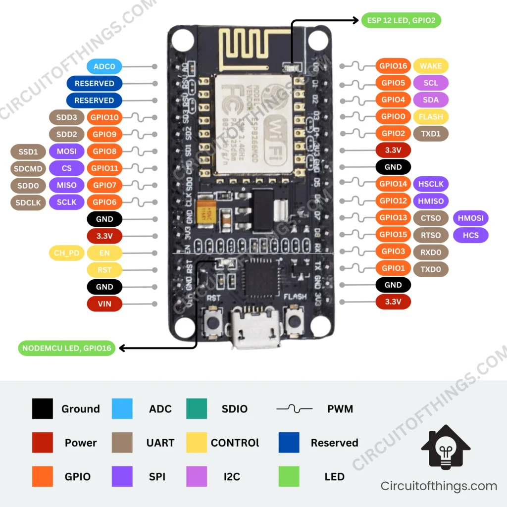
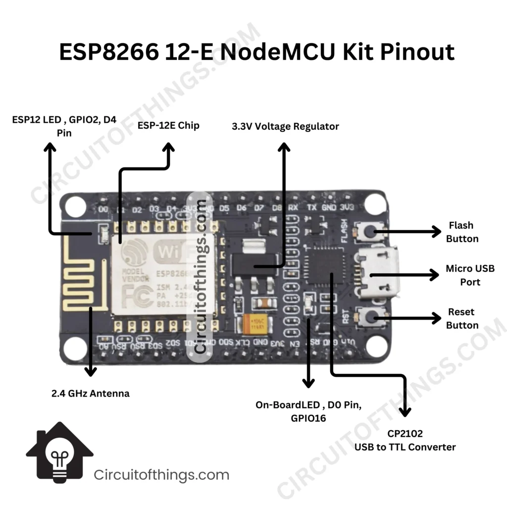
NodeMCU Pinout Diagram
The NodeMCU pinout is illustrated in the following way:

Nodemcu Pinout Diagrams in PDF Format
We’ve created a convenient PDF that you can download and print to have the ESP8266 diagrams close at hand:
Exploring NodeMCU Pin Functions
Let’s explore each NodeMCU board pin category’s uses in more detail.

Power Pins
VV (3.3V): The components attached to this pin receive a steady 3.3V power supply from this pin. It is crucial to confirm that the peripherals’ voltage needs and this power supply are compatible.
Vin: The Vin pin enables the NodeMCU board to run dependably by providing an external power source within the advised range.
GND: The ground pins provide a common ground reference and act as the system’s reference voltage.
Analog Pins
A0: This pin may read analog voltages in the 0 to 3.3V range. It is helpful for obtaining analog data and interacting with analog sensors.
Digital Pins
These pins designated D0 through D10, enable digital input and output functions. They can be employed to read data from sensors or manage actuators like relays, motors, and LEDs.
UART Pins
- TX: The NodeMCU board’s TX pin is used to communicate serial data to other devices or terminals.
- RX: The RX pin is in charge of accepting serial data from terminals or other external devices.
I2C Pins
- SDA: The I2C communication protocol uses this pin for bidirectional data flow.
- SCL: The clock signal necessary for synchronous data transfer in I2C communication is provided by the SCL pin.
SPI Pins
- MOSI: In SPI communication, this pin acts as the data line for transmitting data from the master to the slave.
- MISO: In SPI communication, the MISO pin manages the data line used to transfer data from the slave to the master.
- SCK: The clock signal for synchronizing data transfer in SPI communication is provided by the SCK pin.
- SS: In SPI communication, the SS pin is utilized to choose the slave device.
Other Pins
- RESET: To reset the NodeMCU microcontroller, use the RESET pin.
- D8: This pin, which is attached to the NodeMCU board’s integrated LED, can be used for basic visual cues.
Which ESP8266 / Nodemcu GPIOs are safe to use?
It’s critical to know which GPIO (General Purpose Input/Output) pins on the NodeMCU board and other ESP8266-based development boards are safe to utilize. The majority of GPIO pins can be used for a variety of tasks, but a few of them have particular uses or restrictions. The following is a list of the ESP8266’s GPIO pins that are often safe to use:
| GPIO Pin | Pin Name | Safe for General Purpose | Reason |
|---|---|---|---|
| GPIO0 | D3 | Yes | Can be used, but consider boot mode requirements during power-up. |
| GPIO1 | TX | No | Reserved for UART transmission. |
| GPIO2 | D4 | Yes | Can be used as a general-purpose I/O pin. |
| GPIO3 | RX | No | Reserved for UART reception. |
| GPIO4 | D2 | Yes | Can be used as a general-purpose I/O pin. |
| GPIO5 | D1 | Yes | Can be used as a general-purpose I/O pin. |
| GPIO6 | SCL | No | Reserved for I2C communication. |
| GPIO7 | SDA | No | Reserved for I2C communication. |
| GPIO8 | D0 | Yes | Can be used as a general-purpose I/O pin, but has a weak internal pull-up resistor. |
| GPIO9 | SD2 | No | Reserved for SPI communication. |
| GPIO10 | SD3 | No | Reserved for SPI communication. |
| GPIO11 | CLK | No | Reserved for SPI communication. |
| GPIO12 | D6 | Yes | Can be used as a general-purpose I/O pin. |
| GPIO13 | D7 | Yes | Can be used as a general-purpose I/O pin. |
| GPIO14 | D5 | Yes | Can be used as a general-purpose I/O pin. |
| GPIO15 | D8 | Yes | Can be used as a general-purpose I/O pin, but keep low during power-up for proper SPI operation. |
| GPIO16 | D0 | Yes | Can be used as a general-purpose I/O pin. |
Please note that while some GPIO pins are generally safe to use as general-purpose I/O pins, others have specific functions or limitations. It’s important to consult the documentation and pinout diagram of your specific NodeMCU board to ensure accurate and board-specific information.
Considering these guidelines will help you make informed decisions when utilizing the GPIO pins of the NodeMCU pinout board for your general-purpose input/output requirements.
If you have any further questions, feel free to ask! contact us
NodeMCU Pinout Examples
Let’s look at a few real-world examples of how to use the NodeMCU pins in different contexts.
Conclusion
For the NodeMCU to be used efficiently in IoT projects, it is essential to understand the pinout. You can use the NodeMCU pinout to its maximum capacity for your applications by becoming familiar with the various pins and their functions. The NodeMCU is a fantastic option for IoT prototyping and development, regardless of whether you are a novice or an expert developer.
If you liked this article about NodeMCU Pinout: A Comprehensive Guide for Beginners, then please subscribe to our Newsletter for More Articles about aeronautical engineering. You can also find us on Instagram, , and Telegram.
Frequently Asked Questions (FAQs)
What is NodeMCU?
An open-source development board called NodeMCU combines the ESP8266 microcontroller with onboard Wi-Fi, making it perfect for Internet of Things (IoT) projects.
What is a pinout?
A microcontroller’s or development board’s pinout describes the positioning and functions of the pins.
How many digital pins does NodeMCU have?
11 digital pins (D0 to D10) are available on NodeMCU and can be used for digital input and output activities.
Can I use NodeMCU with Arduino IDE?
Yes, NodeMCU is programmable with the Arduino IDE using the well-known Arduino programming language.
What are the power requirements for NodeMCU?
Depending on the recommended voltage range of 4V to 9V, NodeMCU can be supplied by either the VV (3.3V) pin or an external power source attached to the Vin pin.
