- Introduction
- What is the ESP8266-01?
- ESP01 and ESP01S Differences
- Understanding the ESP8266-01 Pinout
- Power Supply and Voltage Requirements
- GPIO (General Purpose Input/Output) Pins
- Analog Pins
- Serial Communication Pins
- Reset and Wakeup Pins
- Connecting the ESP8266-01 to External Components
- Programming the ESP8266-01
- ESP8266-01 Pinout Examples and Projects
- Frequently Asked Questions (FAQs)
- Conclusion
Introduction
Welcome to our in-depth guide to the ESP8266-01 pinout and pin layout. Understanding the pinout of the ESP8266-01 module is critical if you’re an electronics enthusiast or a developer trying to integrate it into your projects. In this post, we will go over the ESP8266-01 pinout in detail, as well as its functions and how to use it successfully in your designs. So, let’s get started!
👉 Need an ESP8266-01 for your project? Buy ESP8266-01 Module Here (Affiliate Link)
What is the ESP8266-01?
Introduction to the ESP8266-01 Module
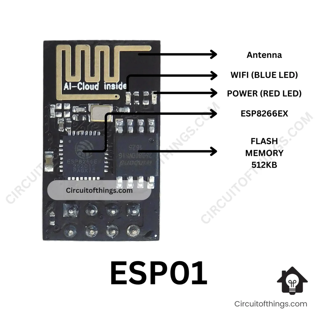
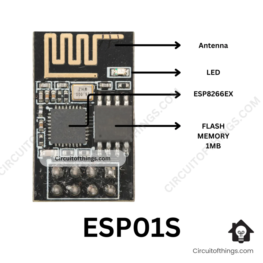
The ESP8266-01 Pinout is a popular and adaptable Wi-Fi module that is frequently utilized in IoT applications and projects. It offers a low-cost and effective way to integrate Wi-Fi capabilities into microcontrollers and other embedded devices. The ESP8266-01 module is small in size, making it excellent for projects with limited space.
ESP8266-01 Pinout

ESP8266-01S Pinout

ESP01 and ESP01S Differences
| Feature | ESP-01 | ESP-01S |
|---|---|---|
| Flash memory | 512 KB | 1 MB |
| Color | Blue | Black |
| Power indicator LED | Yes | No |
| Blue LED wiring | TX pin | GPIO2 pin |
| Onboard pull-up resistors | 1 (CH_PD) | 3 (CH_PD, GPIO0, GPIO15) |
| AI Cloud Inside branding | No | Yes (some modules) |
Key Features and Specifications
Among the prominent features and characteristics of the ESP8266-01 module are:
- Wi-Fi capabilities are built in.
- Digital input/output GPIO pins
- Pins for analog input
- Communication using UART (Universal Asynchronous Receiver-Transmitter)
- Power usage is minimal.
- The form factor is small.
Now that we’ve covered the basics of the ESP8266-01 Pinout, let’s go deeper into its pinout.
Understanding the ESP8266-01 Pinout
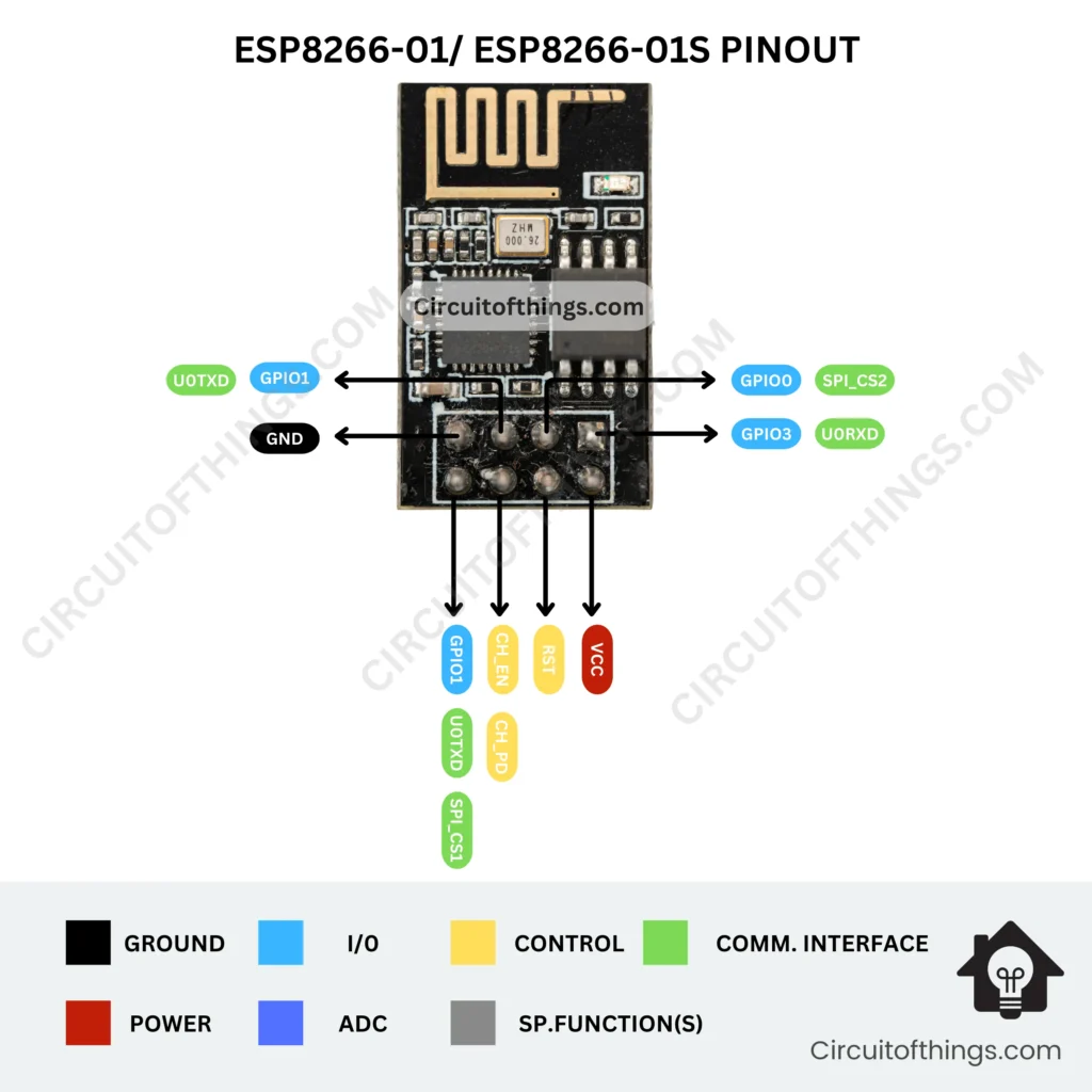
The ESP8266-01 pinout is made up of multiple pins, each having its own set of operations and capabilities. Understanding the pin setup is critical for using the module successfully in your applications. Let’s have a look at the pin layout and functionality of the ESP8266-01.
| Pin Name | Function |
|---|---|
| VCC | Power supply (3.3V) |
| GND | Ground |
| GPIO0 | General-purpose I/O 0 |
| GPIO2 | General-purpose I/O 2 |
| GPIO1 | General-purpose I/O 1 |
| RST | Reset |
| CH_PD | Chip Power-down |
| TX | Transmit (UART) |
| RX | Receive (UART) |
Pin Functions and Descriptions
- VCC: This pin provides the ESP8266-01 module with its power supply voltage (3.3V).
- GND: This pin connects to the reference ground.
- GPIO0: stands for general-purpose input/output pin. It offers a variety of features, including GPIO boot mode selection, and flash programming.
- GPIO2: Another GPIO-enabled general-purpose input/output pin.
- GPIO1: This pin also functions as a general-purpose input/output.
- RST: The reset pin is used to return the module to its factory settings.
- CH_PD: stands for Chip Power-down Pin. By connecting this pin to VCC, the module is enabled.
- TX: UART communication transmit pin.
- RX: UART communication receives the pin.
How to Identify Each Pin
It is critical to identify each pin on the ESP8266-01 & ESP8266-01S module for correct connection and operation. The following pinout diagram depicts the layout and pin numbers of the ESP8266-01 module:

Power Supply and Voltage Requirements
The correct powering of the ESP8266-01 module is critical for its maximum performance and reliability. Let’s talk about the module’s power supply options and voltage requirements.
Powering the ESP8266-01 Module
The ESP8266-01 module is powered by a 3.3V supply. Connect the VCC pin to a regulated 3.3V power source to power the module. It is critical to maintain a consistent power source to avoid sudden resets and other problems.
Voltage Specifications and Considerations
When working with the ESP8266-01 module, it’s critical to keep the voltage levels of the signals connected to its pins in mind. Because the module uses 3.3V logic levels, all input or output signals must be compatible with this voltage range. Connecting higher voltage signals directly to the module’s pins may result in damage or erroneous operation.
Level-shifting circuits or voltage translators can be used to connect the ESP8266-01 module to microcontrollers or other devices that operate at different voltage levels.
GPIO (General Purpose Input/Output) Pins
The ESP8266-01 module’s GPIO pins support digital input and output activities. Let’s look at the GPIO pins and what they can do.
Using GPIO Pins for Digital Input/Output
The ESP8266-01 module includes a number of GPIO pins that can be configured as inputs or outputs. These pins allow you to connect to numerous sensors, actuators, and other digital components.
The three available GPIO pins on the ESP8266-01 module are GPIO0, GPIO2, and GPIO1. These pins can be used as general-purpose I/O pins, allowing you to control or read the state of external devices.
Pin Configurations and Capabilities
GPIO0: This pin performs a variety of functions, including digital input/output and boot mode selection. For regular operation, the GPIO0 pin should be pulled high (connected to VCC) at power-up.
To use the GPIO0 pin as a digital output, set its state to high (3.3V) or low (0V) using appropriate programming approaches. The GPIO0 pin, similarly, can be used as a digital input to read the status of an external device or sensor.
The ESP8266-01 module has two more GPIO pins, GPIO2 and GPIO1. These pins, like GPIO0, can be configured as digital inputs or outputs, allowing you to communicate with different components in your projects.
When using the GPIO pins, make sure that the voltage levels of the signals you connect are compatible with the 3.3V logic levels of the ESP8266-01 module. If you need to connect the module to devices that operate at various voltage levels, you can use level-shifting circuits or voltage translators to ensure correct signal compatibility.
Analog Pins
The ESP8266-01 module includes analog input capabilities in addition to digital I/O pins. Let’s take a closer look at the analog pins and how they work.
Overview of the Analog Pins on the ESP8266-01 Pinout
While the ESP8266-01 module is most recognized for its digital capabilities, it also has a few analog input pins. You can read analog voltages from sensors or other analog devices using these analog pins.
It’s worth noting, though, that the ESP8266-01 module features a low-resolution analog-to-digital converter (ADC). The module’s ADC typically has a resolution of 10 bits, allowing analog voltages to be converted into digital values ranging from 0 to 1023.
Analog-to-Digital Conversion (ADC) Capabilities
You can utilize analog-to-digital conversion techniques in your programming to access the analog pins on the ESP8266-01 module. By reading the analog input voltage, you may convert it to a digital value utilizing the module’s ADC capabilities.
It is worth noting that the ESP8266-01 module may not be the best choice for projects requiring precise analog measurements due to the limited number of analog ports and the lower resolution of the ADC. However, for many applications, the module’s analog input capabilities are sufficient.
Serial Communication Pins
UART (Universal Asynchronous Receiver-Transmitter) communication is supported by the ESP8266-01 module, allowing for serial data transmission and reception. Let’s look at the module’s serial communication pins.
Utilizing UART Communication
UART is a serial communication technology that allows data to be transmitted and received between devices. TX (transmit) and RX (receive) UART pins are available on the ESP8266-01 module.
To send data from the module, connect the TX pin of the ESP8266-01 module to the RX pin of another device, such as a microcontroller or a computer. Similarly, the module’s RX pin is used to receive data from an external device.
You may establish dependable serial connections between the ESP8266-01 module and other devices in your project by utilizing UART communication.
Reset and Wakeup Pins
The ESP8266-01 module has pins for resetting the module and using its wakeup feature. Let’s have a look at these pins and their functions.
The RESET Pin and Its Function
The ESP8266-01 module’s RESET pin is used to return the module to its default condition. The module resets when the RESET pin is briefly pulled low (connected to the ground), clearing its internal state and restarting its functions.
The RESET pin is very handy if you run into problems with the module’s functionality or need to restart it during development or testing.
Utilizing the ESP8266-01 Wakeup Feature
The ESP8266-01 module also has a wakeup capability that lets it go into low-power mode and save energy. This functionality is especially useful for battery-powered applications where power consumption must be kept to a minimum.
The wakeup pin, which is usually labeled RST, can be used to wake up the module from sleep or deep sleep. The module can be induced to wake up and resume regular operation by briefly pushing the RST pin low.
For detailed information on how to use the wakeup feature efficiently, consult to the ESP8266-01 module’s documentation and programming standards.
Connecting the ESP8266-01 to External Components
The flexibility of the ESP8266-01 module to interface with many external components and devices is one of its primary advantages. Let’s have a look at how to connect the module to sensors, actuators, and other components.
Interfacing Sensors, Actuators, and Other Devices
The ESP8266-01 module’s GPIO Pins provide a flexible connection with a wide range of external components. The module can serve as a dependable interface for connecting sensors to obtain environmental data or controlling actuators to accomplish certain operations.
To connect external components, you must first locate the GPIO Pins that correspond to the desired functionality. For example, if you require digital input or output, you can use GPIO0, GPIO2, and GPIO1. Similarly, if the analog input is required, the sensors can be connected to the appropriate analog pins.
When integrating external components with the ESP8266-01 module, it is critical to follow correct circuit design practices and ensure that the voltage levels, signal compatibility, and power requirements of the external components are appropriately considered.
Programming the ESP8266-01
To fully utilize the ESP8266-01 module, it must be programmed with the appropriate capabilities. Let’s look at the programming possibilities accessible and how to efficiently program the module.
Overview of Programming Options
The ESP8266-01 module supports a variety of programming approaches, allowing you to select the most appropriate way based on your needs and familiarity with various programming environments.
The Arduino IDE (Integrated Development Environment) and the ESP8266 core are two popular ways to program the ESP8266-01 module. This technique provides a familiar programming environment for Arduino developers while also allowing you to access the enormous Arduino ecosystem.
Alternatively, you can use the Espressif IoT Development Framework (ESP-IDF) to program the module, which enables more extensive capabilities and control over the module’s features. The ESP-IDF is especially useful for complicated projects requiring considerable customization and fine-grained control over the ESP8266-01 module.
FTDI Adapter and Programming Headers
To program the ESP8266-01 module, an FTDI (Future Technology Devices International) adapter is normally required. The FTDI adapter acts as a connector between your computer’s USB port and the module’s serial communication pins (TX and RX).
You can establish a communication link and upload your firmware or code to the ESP8266-01 module by connecting the FTDI adapter to the module’s programming headers.
For detailed information on programming the module using the specified programming option, consult to the documentation and guidelines given by the ESP8266-01 module’s vendor.
ESP8266-01 Pinout Examples and Projects
To provide some context, let’s look at a few examples and projects that explain how to use the ESP8266-01 module’s pinout.
Building a Simple LED Control Project
In this example project, we’ll use one of the ESP8266-01 module’s GPIO pins to drive an LED. This project demonstrates the module’s fundamental digital input/output capabilities.
Materials Required:
- ESP8266-01 module
- Breadboard
- LED
- Resistor (220 ohms)
- Jumper wires
Circuit Connections:
- Connect the ESP8266-01 module’s VCC pin to the breadboard’s positive rail.
- Connect the module’s GND pin to the breadboard’s ground rail.
- Connect one end of the resistor to the breadboard’s positive rail.
- Connect the opposite end of the resistor to the LED’s anode (longer leg).
- Connect the cathode (shorter leg) of the LED to a GPIO pin on the ESP8266-01 module (e.g., GPIO0).
- Finally, connect the GPIO0 pin to the breadboard’s ground wire.
Programming the ESP8266-01 Module:
The Arduino IDE and the ESP8266 core will be used to program the ESP8266-01 module. To upload the code, follow the steps below:
- Create a new sketch with the Arduino IDE.
- Copy and paste the following code into the Arduino IDE:
// ESP8266-01 Simple LED Blink
//CIRCUITOFTHINGS.COM

// Pin connected to the LED
const int ledPin = 0; // GPIO0

void setup() {
  pinMode(ledPin, OUTPUT); // Set the LED pin as an output
}

void loop() {
  digitalWrite(ledPin, HIGH); // Turn on the LED
  delay(1000); // Wait for 1 second
  digitalWrite(ledPin, LOW); // Turn off the LED
  delay(1000); // Wait for 1 second
}
- Check that the ESP8266-01 module’s board and port settings in the Arduino IDE are correct.
- To upload the code to the ESP8266-01 module, click the “Upload” button.
Testing the LED Blink
It’s time to test the LED blink capability after successfully uploading the code to the ESP8266-01 module. Check that the LED is properly connected to the module’s GPIO0 (Pin 0).
After the code has been uploaded, the LED should begin blinking at 1-second intervals. The LED will repeatedly turn on for 1 second and then off for 1 second.
If the LED does not blink or behaves strangely, double-check the circuit connections and make sure the code was properly uploaded.
Conclusion
We learned how to make an LED attached to the ESP8266-01 module blink in this article. You can easily make a basic flashing LED project using the ESP8266-01 Pinout module by following the circuit connections and uploading the provided code.
This project can be expanded to create more complicated projects by serving as a starting point for investigating the possibilities of the ESP8266-01 module. To improve your project, experiment with alternative timings, add more LEDs or combine other components.
Remember to consult the datasheet and documentation for the ESP8266-01 module for further information on its pinout.
Frequently Asked Questions (FAQs)
What is the purpose of the ESP8266-01 module?
The ESP8266-01 module is a flexible Wi-Fi module used in IoT (Internet of Things) projects to provide connectivity and communication. It offers a low-cost way to add wireless capabilities to devices and allows for seamless integration with a variety of sensors, actuators, and other components.
Can I use the ESP8266-01 module with the Arduino platform?
Yes, The ESP8266-01 module is compatible with the Arduino platform. Installing the ESP8266 core in the Arduino IDE allows you to write Arduino-compatible code and use the extensive Arduino library ecosystem to create projects with the module.
What is the maximum voltage the ESP8266-01 module can handle?
The ESP8266-01 module is powered by a 3.3V supply. To avoid harming the module, ensure that all signals and power sources connected to it are within this voltage range.
Can I use the ESP8266-01 module for battery-powered projects?
Yes, you can use the ESP8266-01 module in battery-powered projects. However, to maximize battery life, consider power-saving strategies and optimize the module’s power consumption. Energy can be saved by using the module’s deep-sleep mode and carefully managing Wi-Fi connections.
Is the ESP8266-01 module capable of secure communication?
Yes, the ESP8266-01 module supports HTTPS and SSL/TLS communication protocols. You can establish secure connections and protect data transported to and from the module by implementing appropriate encryption and authentication procedures.
Can I update the firmware of the ESP8266-01 module?
Yes, the ESP8266-01 module’s firmware may be upgraded. There are several methods for updating the firmware available, including over-the-air (OTA) updates and the use of the ESP8266 flasher program. It is critical to follow the manufacturer’s instructions and consult the official documentation for the most up-to-date firmware upgrade instructions.
Conclusion
We looked at the ESP8266-01 pinout and its numerous features in this article. The power supply and voltage requirements, digital I/O pins, analog pins, serial communication pins, reset and wakeup pins, and the procedure of attaching the module to external components have all been covered.
Furthermore, we discussed the programming choices for the ESP8266-01 module, such as using the Arduino IDE with the ESP8266 core and the ESP-IDF for more complex development.
Understanding the ESP8266-01 module’s pinout and capabilities allows you to take advantage of its power and variety in your IoT projects, whether you’re controlling sensors and actuators, connecting to Wi-Fi networks, or developing interactive applications.
To ensure correct circuit design and programming practices, always adhere to the manufacturer’s documentation and instructions.
If you have any further questions on ESP8266-01 Pinout, feel free to ask! contact us

5 Comments
Hi Sai, that was really helpful and detailed enough. Best, Zee
I appreciate you sharing this blog post. Thanks Again. Cool.
The second pinout diagram has a mistake; you have GPI01 shown twice.
Thank you for pointing that out! I appreciate you catching the duplicate “GPI01” in the second pinout diagram. I’ll make the correction right away to ensure accuracy. Let me know if there’s anything else you notice.
That is a really good tip especially to those fresh to the blogosphere. Simple but very accurate information… Thanks for sharing this one. A must read post!